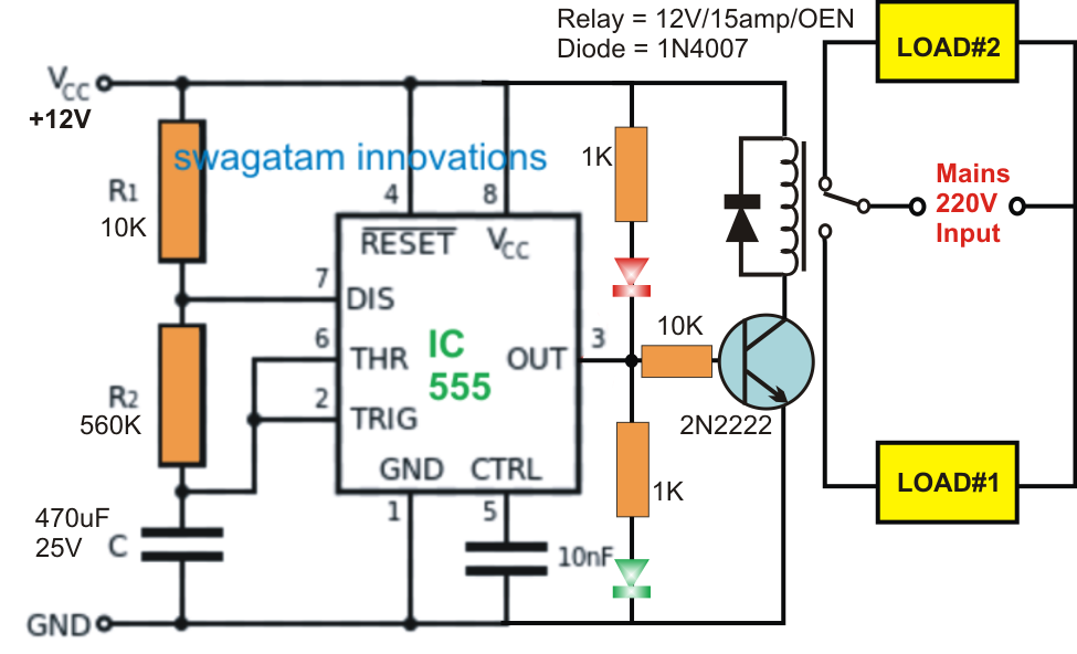
Dancing light using 555 timer 555 timer transistor circuits electronic bjt mosfet npn loads 555 timer circuit calculator astable nagar vishal overview how to make a 555 timer circuit
Simple 555 Timer Circuit
555 timer circuit: how to make pin #3 louder? : r/askelectronics 555 timer circuit diagram project Timer using 555 circuit ic adjustable simple time circuits make termed desired timing component fixing rc resistor altered components above
555 timer circuit using light dancing circuits diagram chip pulse ne555 555timer projects lm555 time electronics astable applications gr next
555 timer ic schematic diagram555 timer schematic circuit Adjustable timer circuit using 555555 timer circuit using light dancing circuits diagram chip pcb pulse easyeda 555timer ne555 projects lm555 time astable software electronics.
How to make a 555 timer circuitSimple 555 timer circuit 555 timer tutorial: how it works and useful example circuits555 timer tutorial and circuits.
![How To Make A 555 Timer Circuit](https://i2.wp.com/img.bhs4.com/b5/2/b528397136061703c7f100e90ba277c4defe80ea_large.jpg)
Digital timer circuit using 555 timer
555 timer tutorial and circuitsSimple timer circuits using ic 555 Simple 555 timer circuitDancing light using 555 timer.
Digital timer circuit using 555 timerTimer 555 circuit diagram 555 timer based inverter circuit diagramDigital clock circuit using 555 timer diagram.
![Simple 555 Timer Circuit](https://i.pinimg.com/originals/7a/60/2c/7a602ca66f44854a1934625085282638.jpg)
How to make a 555 timer circuit
How to make a 555 timer circuitHow to make 555 timer circuit Vishal nagar: how to make 555 timer circuit & 555 timer led flasher?Timer circuits blinking example.
How to make a 555 timer .
![How To Make A 555 Timer](https://4.bp.blogspot.com/-OhcRw79ygHs/T1wfeil_8RI/AAAAAAAAA6g/4udmpV2fTuc/s1600/Delay+ON+Timer+Circuit+Using+IC555.png)
![555 Timer Tutorial: How It Works and Useful Example Circuits](https://i2.wp.com/www.build-electronic-circuits.com/wp-content/uploads/2021/06/555-Timer-BJT-transistor-driver800px-446x500.png)
![Digital Clock Circuit Using 555 Timer Diagram](https://i2.wp.com/www.circuits-diy.com/wp-content/uploads/2021/06/adjustable-timer-circuit-using-555-diagram-schematic-960x720.png)
![Dancing Light using 555 Timer](https://i2.wp.com/electrosome.com/wp-content/uploads/2013/05/Dancing-Light-using-555-Timer-Circuit-Diagram.jpg)
![555 Timer Circuit Diagram Project](https://i2.wp.com/www.electroinvention.co.in/wp-content/uploads/2019/11/IC-555-TIME-delay-circuit-768x660.png)
![Adjustable Timer Circuit using 555](https://i2.wp.com/www.circuits-diy.com/wp-content/uploads/2021/06/adjustable-timer-circuit-using-555.png)
![Simple 555 Timer Circuit](https://i2.wp.com/www.build-electronic-circuits.com/wp-content/uploads/2014/08/555-timer-metronome-circuit-1024x618.png)
![Dancing Light using 555 Timer](https://i2.wp.com/electrosome.com/wp-content/uploads/2013/05/Dancing-Light-using-555-Timer-Circuit-Diagram-600x524.jpg)
![555 Timer Circuit: How to make pin #3 louder? : r/AskElectronics](https://i2.wp.com/i.redd.it/33w1rmk5jjg81.png)
![555 Timer Schematic Circuit](https://2.bp.blogspot.com/-m4OtGGe7XH4/V5DbBTy7iMI/AAAAAAAAOVY/XvaccBIlGRwHeYaKMx-IaIOfmC7nmolLACLcB/s1600/555+timer.png)